Graphic In XAML And WPF
13 January 2008 - WPF
In this article I want to describe the functions of XAML, WPF and Silverlight in the context of graphic. I will use the corporate logo of our new company as the sample for this article because it's XAML implementation uses quite a lot of the graphic functions of XAML.
Unfortunately I cannot go into all great details in this document. If you are interested in more in-depth information you can either read on in the MSDN Library or (if you are able to read German) you can check out our book about XAML and WPF. Here is what I will discuss in this article:
- From Inkscape to XAML - how to work with design professionals
- Shapes and Drawing Objects - Similarities, differences and when to use what
- Combining Geometry Objects
- Transformation Objects - Building a shadow effect
- Differences between WPF and Silverlight
From Inkscape to XAML
If you are a programmer it is very likely that you have to work together with a design professional whenever it comes to graphic design. In my experience you get the best results if you start thinking about the content, basic layout and design principles before you hire a design professional. We always try to work out a very basic draft of what we want to have and hand this draft over to our design partners. We experienced that the design results we can achieve ourselves are suboptimal simply because we have studied software development and not design. However, the results are also not the best they could be if you are not able to express what you want when you request the design work. This leads us to two important needs:
- One member of your software development team should know about the very basic principles of graphic design. He can be the "communication bridge" between the software technicians and the designers.
- The tools that these people use are quite different from what we as software developers use. In the area of graphic design nearly all of the professionals I know use tools from Adobe (e.g. Adobe Illustrator). You have to find a common denominator for exchanging work with them.
Let us concentrate on the second point for the moment. If you are lucky you can afford Adobe licenses in your software development team, too. There are XAML exporters and converters for Adobe tools on the web. Try them and see if they can help you to build the bridge from development to design. However, these tools are extremely powerful and you have to spend some time to learn how to use them.
Another option is the use of the Microsoft pendants: Microsoft Expression Studio. These tools have a similar functional range as the Adobe tools I mentioned before. The problem is that most design professionals I know do not use them by now. Their biggest advantage is that Microsoft's design tools "speak" XAML natively. Their XAML export capabilities are very good! However, just like with Adobe-tools it will take you a while to get familiar with Expression.
If you work on a low budget project or you want to use a design program that is a bit easier to use (because of less functions) you could get your hands dirty with an open source design tool: Inkscape. I personally like Inkscape very much. One of the beautiful things of Inkscape is it's file format: It uses SVG (Scalable Vector Graphics). You could use Inkscape to sketch basic layout ideas and pass the SVG file to you design professionals. You can be sure that they can handle SVG; this file format is nothing strange for them. Jon Galloway did an excellent job describing ways to convert SVG to XAML in his blog.
Depending on the tools your design professionals use they can give you back SVG again or they can export XAML directly. If you get SVG back it is quite easy for you to convert it to XAML. Even if your designers create bitmap images and do not use vector oriented tools Inkscape can help. The program has a built in algorithm for vectorizing bitmaps. It is useful, but be prepared for reworking the result of the vectorization process.
Let us take a look how we lived the process when creating our new logo in XAML. The first thing we did was to think about what we wanted. The name of the company was defined (software architects). We started by defining some basic guidelines about how we want our logo to be designed:
- We did not want to have a complex clipart. The logo should consist of the company name using an interesting typeface.
- The name of the company is quite long. Therefore the typeface had to be condensed. Otherwise the ratio of width and height would have been strange.
- ...
The basic idea we gave to our design professional:
Given these design ideas we looked for a font that could be the basis for our logo. After some research we decided to use a subtype of "ITC Franklin Gothic Book" created by the International Typeface Corporation. We recognized that the last three letters of software and the first three of architects are quite similar and decided that we wanted to use that for a graphical effect. As the result we gave the following sketch of our logo (SVG built with Inkscape) together with our written ideas to our design professional.
After first enhancements:
After enhancing the typeface:
In my opinion this is a great example of what difference design professionals can make. In our case the designer took our ideas and enhanced it a little bit. He combined the two words a little bit different to make the effect much more interesting (see images on the right).
As the second step he converted the typeface into paths and changed some letters to create a grid that breaks the logo into different horizontal parts. Additionally he created an enhanced version of the logo including gradient brushes and a reflection:

After a short while we had the logo in Inkscape (SVG format) as a vector graphic:
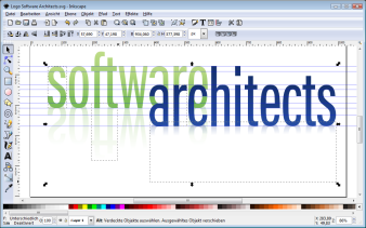
From that point on we were back in our original profession - CODE. In the SVG file we had all the path expressions of our logo ready to be copied out. We could use them without any change in XAML. Here ist an example of a path expression in SVG:
As you can see the path is defined using a mini-language in which all points, lines and curves are specified. This mini-language is very, very similar between XAML and SVG. Usually you can copy the paths from SVG to XAML without any change.
You can find detailed information about path specifications in SVG at W3C and about paths in XAML at Microsoft's MSDN Library.

Shapes and Drawing Objects
The next step is the implementation of the logo in XAML. In XAML you have two possibilities for how to specify graphic objects: You can either use the classes derived from Shape (e.g.Rectangle, Ellipse, etc.) or you use Drawing Objects (classes derived from Drawing). The following UML class diagram from our book "XAML und WPF Programmierhandbuch" shows the inheritance tree of 2D graphic-related classes in WPF:
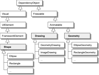
XAML und WPF Programmierhandbuch
Figure 7.10, Page 442
The main differences between Shapes and Drawing Objects are:
- Shapes are Framework Elements. Because of that you can use them in your user interface just like any other control (e.g. Button, TextBox, etc.). They are also derived from Visual. Therefore they now themselves how to render them.
Freezables that are in read-only state are called "Frozen Freezables".
- Drawing Objects are no Framework Elements! They are Freezables (derived fromFreezable). Therefore they can be set into a read-only state. With this you can significantly enhance performance. However, Freezables in ready-only state cannot be modified using animations or data bindings. This leads to the conclusion that you should only "freeze" Freezables if they represent static graphics without changes during runtime.
- Drawing Objects are no Visuals! To display Drawing Objects you need a Framework Element helper object. The following figure shows this relationship.
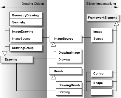
XAML und WPF Programmierhandbuch
Figure 7.27, Page 467
At the first glance Geometries (objects derived from Geometry) seem to be similar as Shapes. Actually they are quite different. Geometries do not represent graphical objects that are ready to be displayed on the screen. They just specify the shape of an object.
In our case it makes sense to use Drawing Objects to implement the logo because it is a relatively static graphical object. Here is the XAML code for the basic shapes of the logo:
Note the namespace declaration forPresentationOptions. You need this to be able to freeze Freezables.
<Page
  xmlns="http://schemas.microsoft.com/winfx/2006/xaml/presentation"
  xmlns:x="http://schemas.microsoft.com/winfx/2006/xaml"
  xmlns:PresentationOptions=
    "http://schemas.microsoft.com/winfx/2006/xaml/presentation/options"
  xmlns:mc="http://schemas.openxmlformats.org/markup-compatibility/2006"
  mc:Ignorable="PresentationOptions" >
We put the logo into the page's resource collection. Thus the logo could easily be extracted into a separate XAML file (e.g. App.xaml or another file).
<Page.Resources>
Here you can see the declaration of the two graphic objects ("software" and "architects"). Note that we use frozen Drawing objects.
You should also take a look at how we combine multiple PathGeometry-objects using GeometryGroup. I will go into details concerning this class later.
    <!-- ****** SOFTWARE ******************************************* -->
    <!-- Geometry for the word "software" -->
    <GeometryGroup x:Key="LogoSoftware"
      PresentationOptions:Freeze="True" >
      <PathGeometry Figures="M 0.31163807,145.75739 ... z" />
      <PathGeometry Figures="M 70.074606,115.57876 ... z" />
      <PathGeometry Figures="M 173.53291,0.40830421 ... z" />
      <PathGeometry Figures="M 307.03223,184.21003 ... z" />
      <PathGeometry Figures="M 391.22711,96.183574 ... z" />
      <PathGeometry Figures="M 426.25331,184.22683 ... z" />
      <PathGeometry Figures="M 501.63047,145.55673 ... z" />
    </GeometryGroup>

    <!-- ****** ARCHITECTS **************************************** -->
    <!-- Geometry for the word "architects" -->
    <GeometryGroup x:Key="LogoArchitects"
      PresentationOptions:Freeze="True" >
      <PathGeometry Figures="M 391.29841,156.18357 ... z" />
      <PathGeometry Figures="M 426.35415,242.80498 ... z" />
      <PathGeometry Figures="M 590.3878,242.94013 ... z" />
      <PathGeometry Figures="M 625.36802,242.94013 ... z" />
      <PathGeometry Figures="M 682.10338,226.72431 ... z" />
      <PathGeometry Figures="M 735.83215,206.36345 ... z" />
      <PathGeometry Figures="M 502.24129,206.22951 ... z" />
      <PathGeometry Figures="M 805.67431,206.22951 ... z" />
      <PathGeometry Figures="M 869.59918,226.66181 ... z" />
      <PathGeometry Figures="M 873.62206,206.17249 ... z" />
    </GeometryGroup>
Here we define the gradient brushes used in the logo.
    <!-- ****** BRUSHES ******************************************* -->
    <!-- Brush for the word "software" -->
    <LinearGradientBrush x:Key="SoftwareBrush" StartPoint="0,1"
      EndPoint="0,0" PresentationOptions:Freeze="True">
      <GradientStop Color="#76ba52" Offset="0.0" />
      <GradientStop Color="#c0dd89" Offset="1.0" />
    </LinearGradientBrush>

    <!-- Brush for the word "architects" -->
    <LinearGradientBrush x:Key="ArchitectsBrush" StartPoint="0,1"
      EndPoint="0,0" PresentationOptions:Freeze="True">
      <GradientStop Color="#264da6" Offset="0.0" />
      <GradientStop Color="#15306c" Offset="1.0" />
    </LinearGradientBrush>
As we said before Drawing Objects needs a Framework Element helper to display them on the screen. In our case the class Image is used for that. Image needs a descendant ofImageSource as the source of the image. For this reason we provide a DrawingImage-object (DrawingImage derives fromImageSource) in the resource dictionary.
<!-- ****** LOGO ********************************************** -->
<DrawingImage x:Key="SoftwareArchitectsLogo"
PresentationOptions:Freeze="True" >
<DrawingImage.Drawing>
<DrawingGroup>
<GeometryDrawing Brush="{StaticResource SoftwareBrush}"
Geometry="{StaticResource LogoSoftware}" />
<GeometryDrawing Brush="{StaticResource ArchitectsBrush}"
Geometry="{StaticResource LogoArchitects}" />
</DrawingGroup>
</DrawingImage.Drawing>
</DrawingImage>
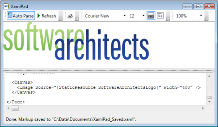
</Page.Resources>Three lines of code are enough to display the logo in any WPF window or page. Everything else is defined in the resources.
  <Canvas>
    <Image Source="{StaticResource SoftwareArchitectsLogo}" />
  </Canvas>
</Page>
Here you can see the logo implemented with the code shown above in XAMLPad. XAMLPad is a small tool with which you can prototype your XAML code. It is included in the free Windows SDK.
Combining Geometry Objects
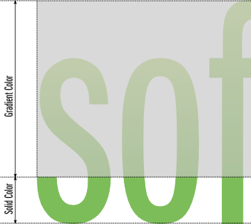
In WPF you have two possibilities to combine Geometries. You can either group them in a collection as shown in the code above. In this case you use the class GeometryGroup. Be aware that GeometryGroup is really just a collection and nothing more. If you want to build a completely new Geometry by combining two others (e.g. intersection, union, etc.) you have to use CombinedGeometry instead.
In our case we use a combination of two Geometries to create the solid color bottom of the word "software". The goal is not to create separate paths for this area of the logo. Instead we want to build on the previously declared path and exclude the gray rectangle (see picture below) from it.
<Page.Resources>
[...]
Note how we reference the existing Geometry of the word "software" by using theStaticResource-Markup Extension.
  <!-- Geometry for the dark area at the bottom of the letters
       of the word "software" -->
  <CombinedGeometry x:Key="LogoSoftwareBottomShape"
    GeometryCombineMode="Exclude"
    Geometry1="{StaticResource LogoSoftware}"
    PresentationOptions:Freeze="True">
    <CombinedGeometry.Geometry2>
      <RectangleGeometry Rect="0,0,519,145" />
    </CombinedGeometry.Geometry2>
  </CombinedGeometry>

  [...]

  <!-- Brush for the dark area at the bottom of the letters
       of the word "software" -->
  <SolidColorBrush x:Key="SoftwareBottomShapeBrush"
    Color="#76BA52" PresentationOptions:Freeze="True" />

  [...]

  <!-- ****** LOGO ********************************************** -->
  <DrawingImage x:Key="SoftwareArchitectsLogo"
    PresentationOptions:Freeze="True" >
    <DrawingImage.Drawing>
      <DrawingGroup>
        <GeometryDrawing Brush="{StaticResource SoftwareBrush}"
          Geometry="{StaticResource LogoSoftware}" />
        <GeometryDrawing
          Brush="{StaticResource SoftwareBottomShapeBrush}"
          Geometry="{StaticResource LogoSoftwareBottomShape}" />
        <GeometryDrawing Brush="{StaticResource ArchitectsBrush}"
          Geometry="{StaticResource LogoArchitects}" />
      </DrawingGroup>
    </DrawingImage.Drawing>
  </DrawingImage>

</Page.Resources>
Transformation Objects
The last piece that is missing to complete the logo is the reflection effect of the two words. The effect can be created by flipping them on the Y axis. For such cases WPF offers the classTransform. The library contains various decendent classes of Transform with which you can create different effects. The following figure gives an overview about what is there for your use:
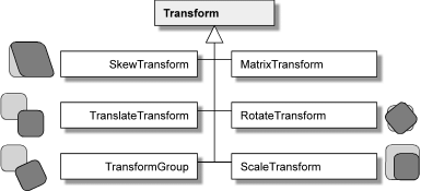
XAML und WPF Programmierhandbuch
Figure 7.39, Page 484
In our case we do not only use a Transform-object. Additionally we use CombinedGeometry to truncate the mirrored words. If we would not do that objects that follow the logo horizontally would show a strange distance from the logo.
<Page.Resources>
[...]

  <!-- Geometry for the mirror-effect of the word "software" -->
  <CombinedGeometry x:Key="LogoSoftwareMirror"
    GeometryCombineMode="Exclude"
    PresentationOptions:Freeze="True">
    <CombinedGeometry.Geometry1>
      <GeometryGroup>
        <PathGeometry Figures="M 0.31163807,145.75739 ... z" />
        <PathGeometry Figures="M 70.074606,115.57876 ... z" />
        <PathGeometry Figures="M 173.53291,0.40830421 ... z" />
        <PathGeometry Figures="M 307.03223,184.21003 ... z" />
        <PathGeometry Figures="M 391.22711,96.183574 ... z" />
        <PathGeometry Figures="M 426.25331,184.22683 ... z" />
        <PathGeometry Figures="M 501.63047,145.55673 ... z" />
      </GeometryGroup>
    </CombinedGeometry.Geometry1>
    <CombinedGeometry.Geometry2>
      <RectangleGeometry Rect="0,0,519,145" />
    </CombinedGeometry.Geometry2>
You can apply a transformation by assigning the appropriate decendent class ofTransform to the Transform-property of the object you want to change.
<CombinedGeometry.Transform>
<TransformGroup>
<ScaleTransform CenterY="184" ScaleY="-1" />
</TransformGroup>
</CombinedGeometry.Transform>
</CombinedGeometry>
[...]
<!-- Geometry for the mirror-effect of the word "architects" -->
<CombinedGeometry x:Key="LogoArchitectsMirror"
GeometryCombineMode="Exclude"
PresentationOptions:Freeze="True">
<CombinedGeometry.Geometry1>
<GeometryGroup PresentationOptions:Freeze="True" >
<PathGeometry .../>
[...]
</GeometryGroup>
</CombinedGeometry.Geometry1>
<CombinedGeometry.Geometry2>
<RectangleGeometry Rect="330,0,604,206" />
</CombinedGeometry.Geometry2>
<CombinedGeometry.Transform>
<TransformGroup>
<ScaleTransform CenterY="243" ScaleY="-1" />
</TransformGroup>
</CombinedGeometry.Transform>
</CombinedGeometry>
[...]
<!-- Brush for the mirror-effect of the word "software" -->
<LinearGradientBrush x:Key="SoftwareMirrorBrush" StartPoint="0,1"
EndPoint="0,0" PresentationOptions:Freeze="True">
<GradientStop Color="#0076ba52" Offset="0.4" />
<GradientStop Color="#60c0dd89" Offset="1.0" />
</LinearGradientBrush>
<!-- Brush for the mirror-effect of the word "architects" -->
<LinearGradientBrush x:Key="ArchitectsMirrorBrush" StartPoint="0,1"
EndPoint="0,0" PresentationOptions:Freeze="True">
<GradientStop Color="#00264da6" Offset="0" />
<GradientStop Color="#3015306c" Offset="1.0" />
</LinearGradientBrush>
[...]
<!-- ****** LOGO ********************************************** -->
<DrawingImage x:Key="SoftwareArchitectsLogo"
PresentationOptions:Freeze="True" >
<DrawingImage.Drawing>
<DrawingGroup>
<GeometryDrawing Brush="{StaticResource SoftwareBrush}"
Geometry="{StaticResource LogoSoftware}" />
<GeometryDrawing Brush="{StaticResource SoftwareMirrorBrush}"
Geometry="{StaticResource LogoSoftwareMirror}" />
<GeometryDrawing
Brush="{StaticResource SoftwareBottomShapeBrush}"
Geometry="{StaticResource LogoSoftwareBottomShape}" />
<GeometryDrawing Brush="{StaticResource ArchitectsBrush}"
Geometry="{StaticResource LogoArchitects}" />
<GeometryDrawing Brush="{StaticResource ArchitectsMirrorBrush}"
Geometry="{StaticResource LogoArchitectsMirror}" />
</DrawingGroup>
</DrawingImage.Drawing>
</DrawingImage>
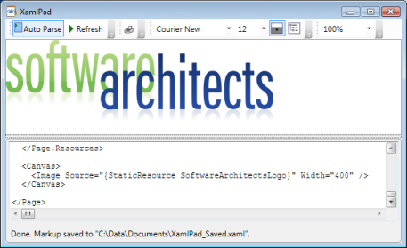
</Page.Resources>This is the finished logo with all effects in XAMLPad.
If you have .NET 3 installed you can also view the Logo in XAML format.
Differences between WPF and Silverlight
Silverlight is Microsoft's answer to Adobe's Flash. Just like WPF Silverlight uses XAML to specify an object tree that represents the user interface elements. If you know WPF's XAML it will not be difficult for you to start with Silverlight. Unfortunately Silverlight's XAML does not offer all the functionality you are used to in WPF.
We are talking about Silverlight 1.0 (which is the version that currently is RTM) here.
I do not want to give a complete listing of all the differences because you can read that in every detail at Microsoft's Silverlight Dev Center in the MSDN Library. I just want to name the differences that affected us when implementing our logo for the use in Silverlight applications. In contrast to WPF's XAML Silverlight does not...
- ...have support for resources to the extent WPF has. Silverlight resources just holdStoryboard-objects used for animation.
- ...know about Freezables.
- ...support the mini-language for path expressions in PathGeometry. It is just supported in Path.
- ...know Markup Extensions like {StaticResource ...} or {Binding ...}. You have to implement the corresponding functionality yourself using JavaScript.
Here is the source code of an implementation of a simplified version of the logo in Silverlight. You can see how similar the Silverlight version is to the WPF version.
Note that there is no reference related to freezing Freezables in the Silverlight version. Silverlight does not know Freezables.
<Canvas
  xmlns="http://schemas.microsoft.com/winfx/2006/xaml/presentation"
  xmlns:x="http://schemas.microsoft.com/winfx/2006/xaml"
  xmlns:mc="http://schemas.openxmlformats.org/markup-compatibility/2006" >

  <Path x:Name="SoftwarePath"
    Data="M 0.31163807,145.75739 ... z">
    <Path.Fill>
      <LinearGradientBrush StartPoint="0,1" EndPoint="0,0">
        <GradientStop Color="#76ba52" Offset="0.0" />
        <GradientStop Color="#c0dd89" Offset="1.0" />
      </LinearGradientBrush>
    </Path.Fill>
    <Path.RenderTransform>
      <TransformGroup>
        <ScaleTransform ScaleX="0.25" ScaleY="0.25" />
        <TranslateTransform x:Name="SoftwareTranslateAnimation" />
      </TransformGroup>
    </Path.RenderTransform>
For demonstration purposes we added a small animation here. We used DoubleAnimation-objects to let the logo fly and fade in.
    <Path.Triggers>
      <EventTrigger RoutedEvent="Path.Loaded">
        <BeginStoryboard>
          <Storyboard>
            <DoubleAnimation
              Storyboard.TargetName="SoftwareTranslateAnimation"
              Storyboard.TargetProperty="Y"
              From="-50" To="0" Duration="0:0:0.5" />
            <DoubleAnimation
              Storyboard.TargetName="SoftwarePath"
              Storyboard.TargetProperty="Opacity"
              From="0" To="1" Duration="0:0:0.5" />
          </Storyboard>
        </BeginStoryboard>
      </EventTrigger>
    </Path.Triggers>
  </Path>

  <Path x:Name="ArchitectsPath"
    Data="M 391.29841,156.18357 ... z">
    <Path.Fill>
      <LinearGradientBrush StartPoint="0,1" EndPoint="0,0">
        <GradientStop Color="#264da6" Offset="0.0" />
        <GradientStop Color="#15306c" Offset="1.0" />
      </LinearGradientBrush>
    </Path.Fill>
    <Path.RenderTransform>
      <TransformGroup>
        <ScaleTransform ScaleX="0.25" ScaleY="0.25" />
        <TranslateTransform x:Name="ArchitectsTranslateAnimation" />
      </TransformGroup>
    </Path.RenderTransform>
    <Path.Triggers>
      <EventTrigger RoutedEvent="Path.Loaded">
        <BeginStoryboard>
          <Storyboard>
            <DoubleAnimation
              Storyboard.TargetName="ArchitectsTranslateAnimation"
              Storyboard.TargetProperty="Y"
              From="50" To="0" Duration="0:0:0.5" />
            <DoubleAnimation
              Storyboard.TargetName="ArchitectsPath"
              Storyboard.TargetProperty="Opacity"
              From="0" To="1" Duration="0:0:0.5" />
          </Storyboard>
        </BeginStoryboard>
      </EventTrigger>
    </Path.Triggers>
  </Path>
</Canvas>
Silverlight does not only work in IE. You can also view the Silverlight-version of the logo in Firefox or other Silverlight-enabled browsers.
Summary
WPF and XAML are great tools to develop next generation Windows applications. In contrast to HTML you do not need to convert all images you want to use in your WPF application into bitmap images. Just let your design professionals deliver the images in a vector-based format and you will find it easy to convert it to XAML.
Content

Tags
.NET (40) ADC (1) Android (1) Angular (4) AngularJS (3) ASP.NET (7) ASPNET Core (1) ASPNET (1) Assembler (1) Azure (62) BASTA (2) Blazor (2) C# (35) C (1) CLI (2) Cloud (1) CoderDojo (1) Conferences and Workshops (2) Container (4) CPP (3) CSharp (5) DevOps (2) Docker (12) Documentation (1) DotNet (1) ECMAScript (1) GAB (1) HTML (2) HTML5 (2) Iron Python (1) JavaScript (3) JWT (1) Markdown (1) MEF (3) Microservices (3) Microsoft (2) Minecraft (2) Mobile (2) Node (1) Node.js (2) NPM (1) OData (5) Presentations (4) Project Management (2) Registry (1) Roslyn (2) Silverlight (3) Software Quality Days (1) SPA (1) SQL (3) SQLCE (1) SVG (1) TechDays (1) Techorama (1) Testing (1) TFS (9) time cockpit (4) TypeScript (18) Visual Studio (37) VSCode (1) VSTS (2) WebAssembly (2) Windows (1) WPF (9) Yarn (1)Authors
Related Posts
BASTA 2013 - C# Workshop
23 September 2013 - .NET, C#, MEF, Visual Studio, WPF
Meine Vorträge auf der BASTA 2013 starten heute mit einem ganztägigen C# Workshop. In diesem Blogartikel stelle ich Unterlagen und Links, die ich dabei verwende, zur Verfügung
dotnet Cologne 2013 - async/await
03 May 2013 - .NET, C#, Visual Studio, WPF
This year at dotnet Cologne I have proposed a 60 minutes live-coding talk about async/await. It was really accepted and I even got the large ballroom. Wow, live coding in front more than 100 developers. This will be awesome. In this blog I post the sample that I am going to develop on stage.